Cone selection is often not given much thought when selecting equipment for a Cone Penetration Testing (CPT) job. It is, however, quite important to consider the soil type that will be encountered as well as the investigation aims of the project. The CPT cone used can have huge impacts on the resulting data quality and applicability and should therefore be carefully considered. This article will break down the various elements of the cone and how they can affect the resultant data. Only electrical CPT is considered.
This is a shortened version, you can download the full article below.
There are several operational benefits of using the digital system. Firstly is the use of universal cables. Unlike analogue CPT, where every measurement parameter needs its own core in the cable (so a 10 pin cable is used for CPT data, while a 16 pin cable is used for seismic CPT), with digital systems universal cables can be used regardless of the data streams generated by extra modules mounted behind the cone. The digital system also allows storage of the calibration file on the cone, eliminating the need for manually adding the latest calibration file to the acquisition software, a potential source of error. Digital CPT is therefore the more future proof option and, with no obvious drawbacks, is the sensible approach for all getting started with CPT.
First introduced in the 1980’s; piezocones, CPT cones that can measure the dynamic porewater pressure during penetration, have become more or less the standard CPT cone. Measuring porewater pressure together with the tip resistance and sleeve friction has a range of benefits, including: easier identification, delineation and characterization of soil layers (as the additional parameter allows for more enhanced correlations), evaluation of the flow and consolidation characteristics through dissipation testing and, most importantly, the ability to correct CPT data for pore pressure effects that will affect the CPT data, whether measured or not.
For that last reason alone, the use of piezocones is the sensible approach for any CPT job.
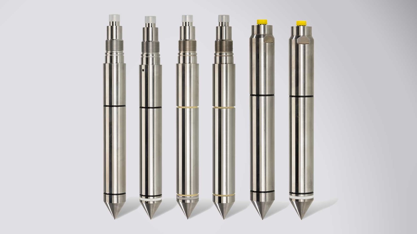
Figure 1: A range of CPT cone penetrometers
It should be noted that a piezocone test, or CPTu as it was originally designated, requires more preparation than a test without pore pressure measurements as the porous filter element must be fully saturated prior to the test to ensure that no air is present within the filter. However, despite the extra care that must be taken, the benefits of obtaining pore pressure data far outweigh the drawbacks.
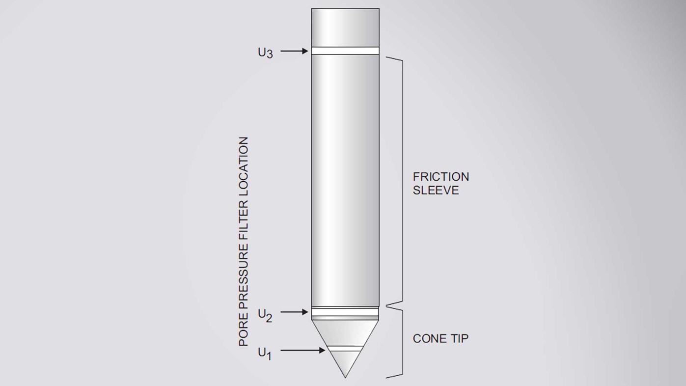
Figure 2: Filter locations | Image source: ASTM D5778
Piezocones are available with the porous filter element in three locations: u1 on the tip midface, u2 at the shoulder and u3 behind the friction sleeve. The majority of piezocone tests are performed with u2 cones and these are typically offered as standard. Tests with the u1 position have the advantage of being the least likely to return negative pore pressures in dilative soils. The u3 filter position is very seldom used, but is useful for correcting friction sleeve data for pore pressure effects and is normally performed only on research projects.
Converting a u2 cone to a u1 cone is very simple as it only involves the replacement of the cone tip. A u3 cone on the other hand requires different cone internals - therefore a u2 cone cannot be converted to a u3 cone very easily.
Porous filters can be made out of plastic such as HDPE or from metal; most commonly brass or bronze, but also steel. Plastic filters are single use whereas, if undamaged, metal filters can be cleaned, re-saturated and reused.
Rather than porous filters, cones are also available with slot filters. The slot filter has an internal cavity which is filled with a thick grease and when the cone is fully assembled a narrow gap, or slot, exists, so the pore pressure can be transferred through the grease to the pressure transducer.
Slot filter elements are less dynamic in their response than porous filter elements, but do have the advantage that they are less likely to desaturate in dry or dilative soils due to the thick grease used.
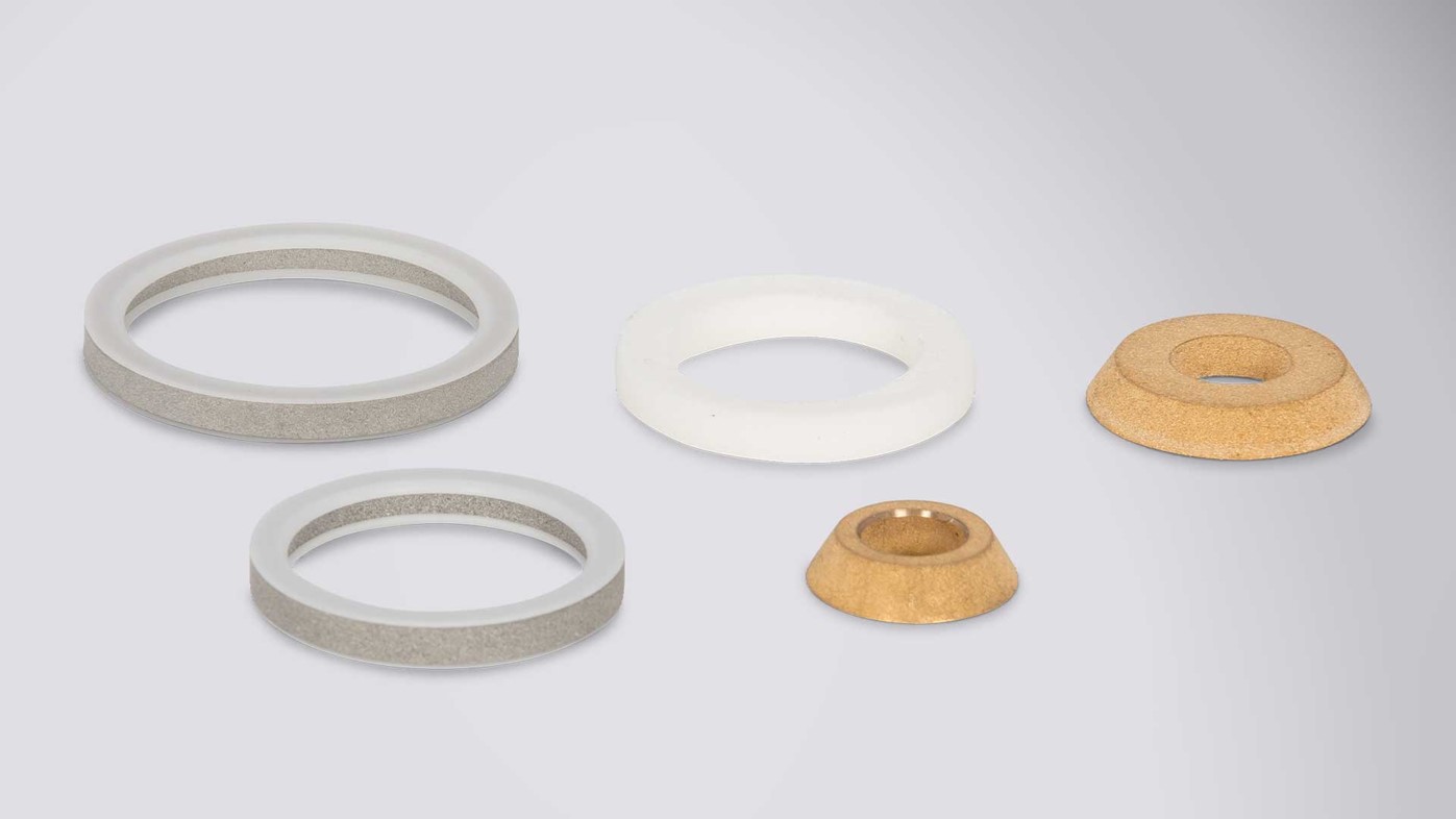
Figure 3: CPT cone filters
Cones are broadly available in two types or loadcell arrangements: subtraction or compression. So which to use? Sleeve friction tends to be a much smaller measurement than cone tip resistance, as typical friction ratios are between 10 and 0.1 %. It therefore follows that measuring sleeve friction on a loadcell designed to have greater sensitivity at small strains will give a more accurate measurement of sleeve friction. Error or inaccuracy of a load cell tends to be approximately 0.5% of its full scale output (FSO), hence load cells with larger FSOs will have larger errors. Thus measuring a very small reading on a loadcell with an large FSO (so that the range covers the cone tip resistance) will easily result in a situation where the reading is close to or even smaller than the inherent error in the reading.
Compression cones are recommended on projects where accurate sleeve friction readings, particularly in very soft materials, are required or on projects where Application Class 1 data is required. For projects where very stiff materials will be encountered or where production is more important than sensitivity, subtraction cones tend to be favoured.
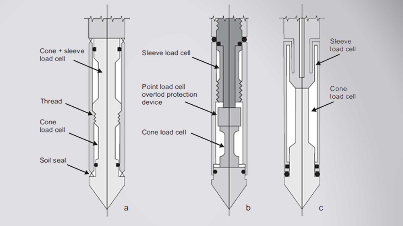
Figure 4: CPT cone loadcell arrangements. a. Subtraction b. Compression c. Tension | Image source: ASTM D5778
Typically CPT cones are designed to work in a range of soils, up to and including very stiff soils where upwards of 50 MPa (522 tsf) cone tip resistances may be encountered and therefore these cones are capable of measuring 75 Mpa (783 tsf) or even 100 MPa (1044 tsf) without being overloaded. However, when testing in predominately soft soils with such a cone it is possible to work only in the bottom 10 or even few % of a cone’s working range and therefore it does not always make sense to use such a high capacity tool. Cones with smaller load cell ranges are more sensitive to small strains and are therefore more accurate in very soft soils.
Even if not offered as standard, cones with smaller measuring ranges are typically available and are a valuable tool in ensuring the most accurate and sensitive data possible when working at small strains, like those encountered in very soft, sensitive soils, such as marine deposits.
CPT cones are sold in a variety of sizes, however the vast majority are 10 cm2 or 15 cm2 with the former being considered by ISO and ASTM as the standard, but the latter being the most commonly used. It should be noted that the size refers to the cross-sectional area of the cone tip, not surface area.
Cones with smaller load cells are more sensitive to small strains. Although it may seem counter intuitive, increasing cone size can also increase sensitivity to small strains. By increasing the surface area, the force imparted by the soil on the cone tip increases and improves the chances that a detectable force is observed in the softest soils.
However modern 10 and 15 cm2 cones are able to detect changes in soil properties in even the softest soils, especially when cones with smaller load cell ranges are used.
Also available are mini cones, typically 5 and 2 cm2 in size. These mini cones are often deployed by lightweight seabed CPT systems as they can be pushed on thinner CPT rods, which can be coiled on a spool and require less reaction force to be pushed into the ground, hence making them perfect for a lightweight system. Mini cones are also used in laboratory settings and calibration chambers.
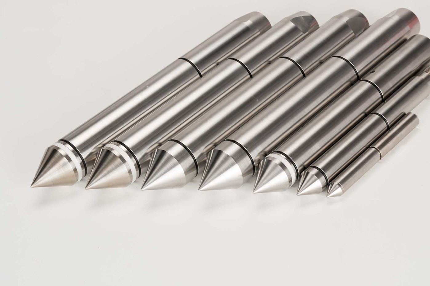
Figure 5: CPT cones ranging in size from 15 to 2 cm2
Add-on modules are a cost and time effective way to expand the data acquired during CPT. These modules can be added to the back of the cone to acquire an extra data set with no impact on the quality of the standard CPT data. Available modules include:
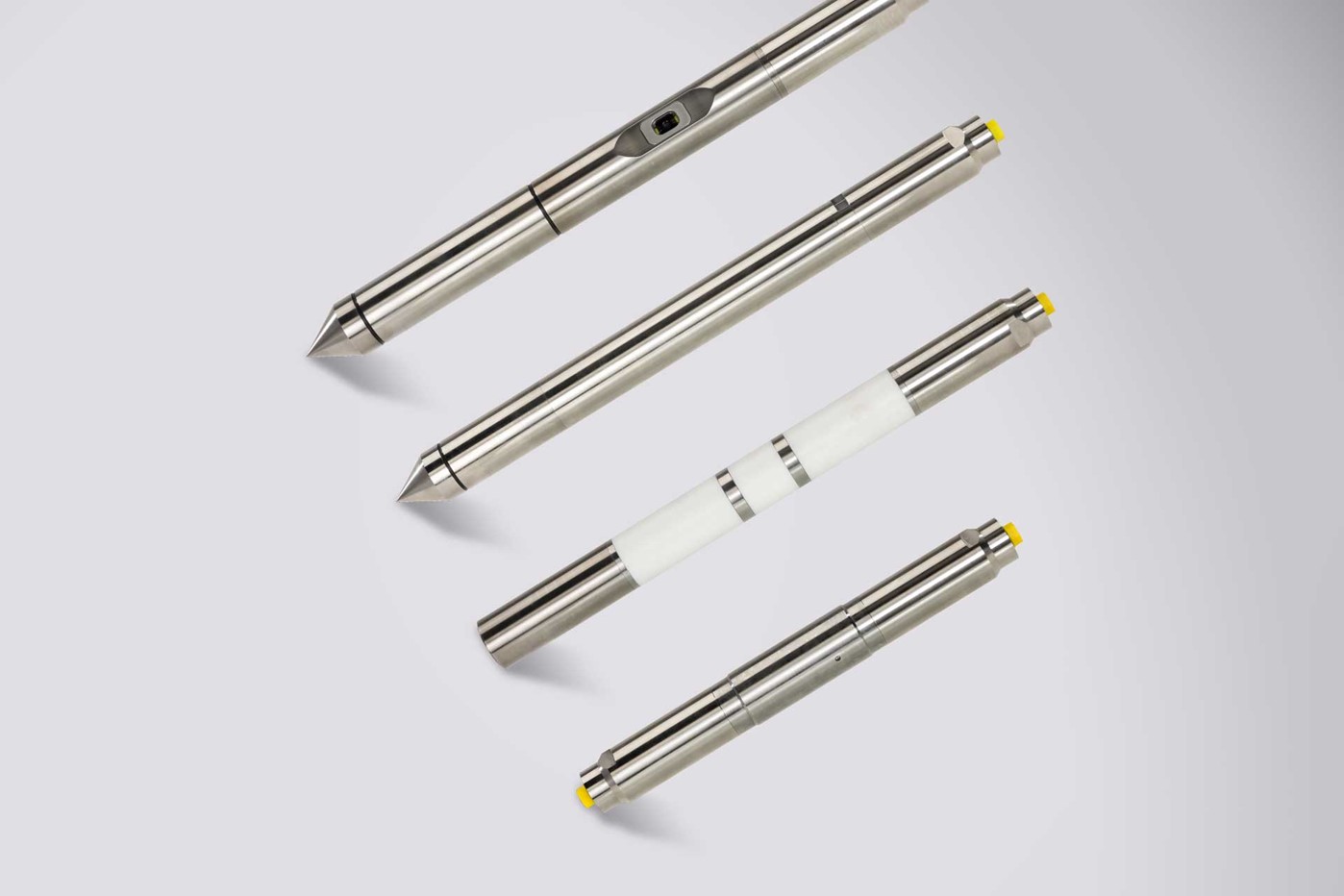
Figure 6: CPT add-on modules
CPT cones come in a variety of types and configurations, the selection of which can have a significant impact on the quality and applicability of the acquired data. At Royal Eijkelkamp it is our goal that our customers are equipped with not only reliable equipment, but also with the correct tools for the job at hand. If you would like more information on any of the topics raised in this document or any aspect of Cone Penetration Testing then please get in touch with one of our CPT experts on CPT@eijkelkamp.com.